![]()
/ Topics / Control Signals
Asset-based, Nonlinear Workflow
On Graphs and Code . Authoring Musical Notes
Player . Instrument . NoteStream . TimeKeeper
Channels, Effects . Control Signals
Audio I/O . MIDI Input . VST3 Plugins
Wherein we discuss the joys of control changes and LFOs
Controllers generate parameter value changes,
Control Changes, at an arbitrary rate. Controllers can change the behavior or sound of any controllable node at any time during a performance. Most Fiddle nodes are at least partially controllable. This means that most parameter values can be modified live via Fiddle's node inspector. It also means that you can control them through your graph.
History, Jargon, Motivation
In the heyday of Analog Synthesis the term LFO (low frequency oscillator)
was introduced to distinguish audio rate signals (those we can hear as a tone)
from lower frequency signals that we can employ to modulate an audio signal.
For example an LFO multiplied by an audio signal can produce a tremolo effect.
For this use, the term LFO is very descriptive. Where the term LFO has
grown into misuse is when it is used to describe trigger signals or more
arbitrary parameter changes that simply can't be said to oscillate.
In a more modern and more general setting we can view audio synthesis as a
collection of algorithms that are glued together through a network of parameters.
In this view, sound changes occur through parameter changes and the choice of the
rate at which the parameters are changed. Now we can say this: to achieve
a tremolo effect we emply an LFO (algorithm) to drive a parameter
change to another algorithm (say, its Gain). And we can also send a CC
that may Trigger an arpeggiator. This admittedly pedantic diatribe is
presented merely to free your mind
from the shackles of historical jargon (and provide you with some new shackles?).
Now couple this with Chuck's unique architecture
and we can see that a more general term for arbitrarily timed parameter changes
is helpful. Following the MIDI v1 jargon, we thus employ the term Control Change,
or CC for this more general setting and this lands us here:
A
Controllersends arbitrarily timed parameter values,Control Changes, to connectedControllables.
A Tour of Controllers
In order for Controllers to independently manage event timing they operate in separate ChucK shreds. If an event has a duration, we say that that controlling-shred is blocked. So, if you wish to schedule two events of overlapping durations you need two controllers and two shreds. Loosely speaking the number of controllers you need is the sum of the number of independent audio channels and the number of parameter "automators".
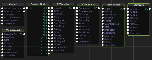
Player is the most common controller. It has two output
ports, Controller and CC. Both ports convey the same signals to connected
nodes but it may be convenient to distinguish Instrument connections from more
general CC signal flow. As CCs flow past a Player it can rename them
by connecting Alias nodes to CCAliases. This idea is further
developed in this example.
SessionGrid is be used to schedule or trigger downstream notestreams like NoteGrid. It can play a role analogous to the Timeline or Session View in most DAWs. The Grid Editor is used to produce the session grids files that drive the Session Grid node.
TimeKeeper can be employed as a controller to
signal important state changes that occur during a performance.
TimeKeeper emits CC triggers like TkStart, TkStop, TkMeasure, TkBeat
and these can be used, for example, to control recording intervals.
We should note that these signals are trigger-like and thus have no duration.
This means that you can wire any number of Controllables to a single
TimeKeeper.
CCSampler is a simple node that produces
a fixed rate CC stream by sampling an arbitrary audio signal that you connect.
You also pick a sample rate, remap input values to a different output range,
and pick the CC name. The result is a very flexible node that can deliver
a multitude of automated CC features that include the typical LFO applications.
To diagnose issues with your setup this node also includes an optional
signal plotting capability.
CCGenerator is very similar to CCSampler.
The primary difference is that it doesn't require an upstream signal to sample.
Rather, a fixed-rate control signal is generated internally from a menu of
simple input signals: Random, Random Walk, Perlin and Sine. Also
because the input signals are limited and well-defined CCGenerator doesn't
include the plotting options.
CCMouse produces a variable-rate control signal
that allows you "paint" control signals with your mouse. CCMouse produces
a number of control signals including MouseX, MouseDX, MouseY, MouseDY,
WheelDY and MouseB1. Values can be scaled and remapped by CCMouse parameters
and these CC names can be remapped via its CCAliases parameter.
PitchTracker is a simple controllable
wrapper for ChucK's PitchTrack Chugin.
This produces a variable-rate control signal that includes NoteOn messages
(but not NoteOff) and thus can be connected to instruments. The result is
akin to auto-tuning especially if you connect a vocal track as input. Note
that this approach is not intended to fill the role of a real auto-tuner but
it can produce interesting results.
A Brief Tour of Controllables
The fact that all nodes that can be edited live are Controllable means
that they can also partake in graph-based control. Even Controllers are
themselves Controllable. Because nearly all Fiddle nodes are Controllable the
same principles apply and we can keep our tour of Controllables brief
and generic. The key indicator of a Controllable is that it has
a Controller input parameter.
Consider this graph:
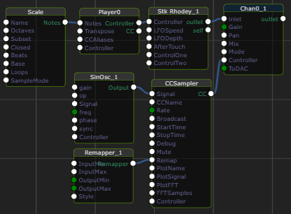
By inspection we see that a CCSampler is plugged into Chan0_1 and thus must be controlling some aspect of the Channel node. Additionally we see that the CCSampler is sampling a SinOsc output, so it's sending a sine wave to the Channel.
The Challenge
Four important facts about the behavior lurk within the node values:
- which parameter of Chan0_1 is being modified
- what is the frequency of the sine wave
- how often is the sine wave sampled to produce a control signal.
- how are the sine wave values (between -1 and 1) remapped to produce the control signal value.
Since we've provided you with the example file we'll leave it as an exercise to the reader to unravel these mysteries.