![]()
/ Examples / AudioIO / Looper
NoteStreams .. Instruments
Filters .. Effects .. LiCK Effects
Plot .. Utility .. Pure ChucK
This example shows how to integrate Fiddle's Looper node into your practice, recording and live-performance sessions. Looper pedals are a familiar tool to most musicians. Fiddle's looper tool is a software pedal. A single Fiddle session can have many loopers running simultaneously, each controlled by your custom mappable MIDI events.
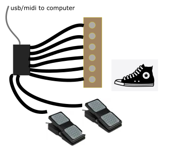
To develop Fiddle's Looper capabilities, we needed access to a typical hands-free control rig. This was exactly the excuse we needed to develop a homemade USB-MIDI device. You can easily purchase MIDI stompboxes and control surfaces but hey, that's too easy. If you are interested in building your own, we've documented and open-sourced the
dbStompbox. You can find more details on github.
Frippertronics forever!This example requires customization according to your rigging. Right-click to copy examples to your workspace
Looper Overview
Looper nodes reside in the Graph Editor and implement live sampling functionality using ChucK's LiSa ugen. Connect an audio source to its inlet. Route the outlet to either an effects chain or directly into the AudioOut node for offline storage. In a live-performance setting, you can remap input control signals from your MIDI stompbox or control surface to modify the Looper state.
In this example we develop a looper rig for guitar jamming. Most of this discussion applies equally well to vocal or really any audio looping performance.
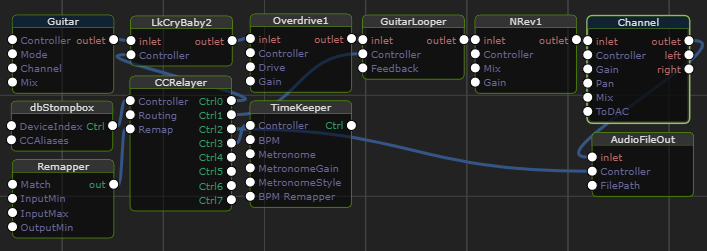
We'll walk through the roles of each node in this rig. Broadly speaking the top
row of this graph represents a typical pedal board. The signal starts
at the top left and is processed by adjacent nodes from left to right.
The Guitar node is actually an AudioIn. For more details on AudioIn
see this example. When the signal encounters a Looper node,
here GuitarLooper, the looper-magic happens.
Nodes present in the second and third rows implement hands-free control over the session.
Looper Node
The Looper Node is the star attraction here so let's start with it.
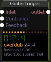
At right you see the GuitarLooper node in an active state. In addition to the usual depiction of node inputs and outputs, we see a custom dashboard of the internal looper state. During performance, the idea is to move between looper modes. You can select a mode from the node inspector parameter, but for hands-free operation you typically trigger the mode change via control-signals.
Here is the Looper's state transition diagram:
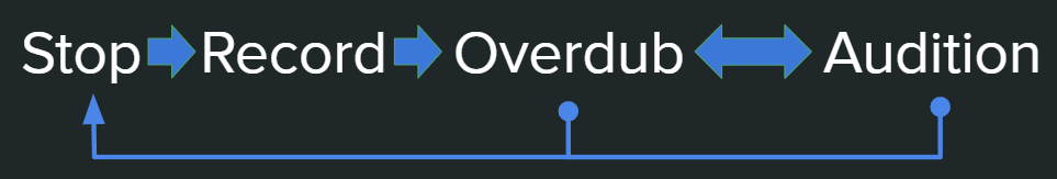
So to get looping, first transition from Stop to Record. Next, transition to Overdub to add more to the loop. If you want to jam over the existing loop without recording, proceed to Audition. From there you can switch freely between Audition and Overdub 'til the cows come home.
On Duration
Observant readers may be asking themselves how do Record and Overdub differ?
Here's the deal: the difference between record and overdub is merely that
the length of the loop is determined while recording. For a pre-determined
loop length, simply provide the number of bars for your loop into the
Duration field. At the point that this duration has elapsed, Looper
automatically transitions from Record to Overdub. If you wish to define
your loop-length during performance, manually change the mode before
the static Duration elapses. This same dichotomy (static vs live) also
applies to establishing the tempo as discussed below.
The loop length is the shorter of the static
Durationand the time at which you manually transition from Recording to Overdubbing.
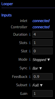
Looper Parameters
Here are the Looper Node parameters. If you opt for live-modification of these parameters, it's possible that the Node Inspector won't reflect the current state of affairs. This is where the custom node dashboard should be relied upon. Just zoom into your graph's live looper nodes before starting a session.
Duration the static loop duration expressed in TimeKeeper bars. A
loop's duration can't be changed in a live session. You can, however
modify the loop subset as discussed below.
Slots the number of Looper slots. Each slot is an equal-duration,
but otherwise independent loop context. You can think of a slot as
a recording take and switch between them live. The number of slots
cannot be changed during a live session. Only a single slot,
the current one, can be heard at a time. If you want to hear
multiple live loopers banging their heads together, just
instantiate multiple Looper nodes.
Slot controls the active slot. In multi-slot operation you can
move between slots with the control signal NextSlot or NextMode (held).
More discussion of control signals can be found below.
Mode controls the current operating mode. When operated manually
it is on you to understand and adhere-to the state-transition diagram
above. In hand-free mode, the NextMode control signal manages the
state transitions with a single click.
Sync controls the all-important timing of the transition from Stopped
to Record. Selected between Bar, Beat or None to ensure that
activity lines up in time the way you like.
Feedback controls the overdub signal loss between loops. At 1 the
signal stays around forever and can easily produce a muddy result.
At 0, the effect of the looper is entirely removed, only the live
signal appears on the output. In this example, we've connected an expression
pedal to the Feedback value via dbStompbox and CCRelayer.
Subset controls the active loop subset. Choose between Full, Half and
Double.
Gain a multiplier for the output signal.
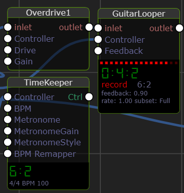
TimeKeeping
Successful looping often requires that you be keenly aware and in control of time. The TimeKeeper node supports these features to help with looping:
Tap Tempo is a control signal that can be delivered by a control surface.
In this example we've wired a footswitch to deliver a Tap message.
Typically you nominate a tempo prior to entering Record. The above discussion
of Duration applies relative to the TimeKeeper tempo at the moment of
recording.
Metronome enables an audible sound on beats and bars according to
the current Metronome Style. The sound is routed directly to ChucK's
global DAC. In this example we route the output of Channel directly to
the AudioFileOut node. When active (as controlled by a Record button in
dbStompbox), the Metronome sound won't be present in the recording. If
you prefer visual feedback, disable the Metronome and zoom in to the
TimeKeeper node during performance and see the measures and beats update live.
At right, notice that the Timekeeper shows the signature, BPM and current
time in its custom node-dashboard area. Further notice that the TimeKeeper
time is also present in the Looper's dashboard and that its loop time is
two measures behind the global time.
Metronome Style chooses the metronome style and is only relevant when
Metronome is enabled. Options are: Bars+Beats, Bars, Beats.
Metronome Gain controls the loudness of the Metronome signal.
Managing Controls
At the heart of performance looping is the requirement to modify the session state fluidly. Whether your "axe" is your voice, a guitar, keyboards or a saxaphone, it's often the case that a computer keyboard or mouse isn't the right tool. This problem is usually solved with a MIDI or USB control surface. The idea is to assign important events to keys, foot pedals, dials or sliders that are adjacent to your instruments.
In this example we employ dbStompbox which is just a homebrew MIDI controller with 6 momentary foot switches and 2 expression pedals. A simple Amazon search reveals a number of similar options ranging in price from US$49 to US$350.
Because selecting a control surface is a personal choice, it's inevitable that this example will require modification to attain a glorious result. So our goal here is to teach fishing, rather than to deliver fish.
CCRelayer Node
The CCRelayer's job is to remap/rename incoming CCs and route them
to specific targets. Following the documentation for your control surface,
the first step is to decide which buttons (knobs, etc) to assign to which
actions. In the case of dbStompbox we have:
Description CC Name Action Pedal 1 CC8 Wah Wah Pedal Pedal 2 CC9 Looper Feedback Footswitch 1 (left) CC64 (available) Footswitch 2 CC65 (available) Footswitch 3 CC66 Enable Record Footswitch 4 CC67 Stop Looper Footswitch 5 CC68 Tap Tempo Footswitch 6 (right) CC69 Looper Mode
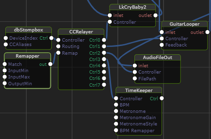
Here's our example graph reorganized to highlight the role of
CCRelayer in the remaining discussion. The important consideration
is that we'd like our single control surface to deliver different
signals to different nodes. For example we want pedal 1, CC8 to
route to LkCryBaby2/Wah (on Ctrl0).
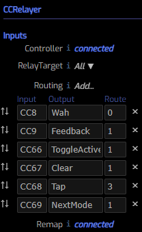
Controller is the input CC source (eg MIDI device) whose signal we
wish to remap and relay. In this example we connect dbStompbox
which is just an instance of the CCMidiDevice
node with its correct MIDI identifier.
RelayTarget parameter selects the downstream target(s). When relaying an
event to a particular output, all nodes downstream from that port receive
it (broadcast). The RelayTarget parameter can be automated. Special values
include None: -2, All: -1. In this example we select All because most of
the work is done by the optional Routing table.
Routing is a table that expresses how an input parameter is routed
to an output port. Here we have six routing rules. These rules are
evaluated for each input signal. Any rules that match produce a result.
This means you can have one input signal remapped to N different output
ports, each with a different name. Referring to the graph image above
you can infer that Footswitch 5 controls the Tap parameter and
is targeting the TimeKeeper connected on output port 3. Also, in this
example we opted to overload the NextMode control signal to also
trigger the NextSlot behavior. This is accomplished thanks to special
support built into the Looper node. If you hold the NextMode button down
for greater than 1.5 seconds, a NextSlot request is inferred. The
advantages of this approach includes improved useability and
footswitch conservation.
Remap allows you to connect any number of Remapper nodes whose
purpose is to modify the values of matching control signals.
In this example, the Remapper node resolves two issues:
- The home-rolled expression pedal only delivered values between 0 and .91. A range of 0 to 1.0 is preferred.
- The Looper's Feedback parameter gives a more natural/controllable result when the parameter values range over .3 to 1. Specifically the zone below .3 deadens the signal too quickly. The remapper prevents this.
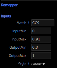
Remapper Node
The Remapper Node is used by CCRelayer to modify the values of
incoming control signals. You can instantiate and connect multiple
Remapper nodes but shouldn't connect more than one per unique signal
name.
Match is the name of the input signal to match.
InputMin the value to consider as the minimum input value. If
the incoming value is below this number it will be clamped.
InputMax the value to consider as the maximum input value. If
the incoming value is above this number it will be clamped.
OutputMin the value to produce when the input is at its minimum.
OutputMax the value to produce when the input is at its maximum.
Style the style of the "connection" between OutputMin and OutputMax.
Common choices include Linear and Exponential.